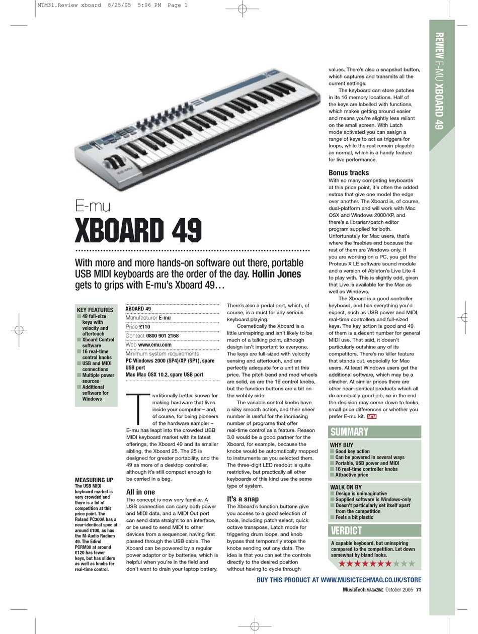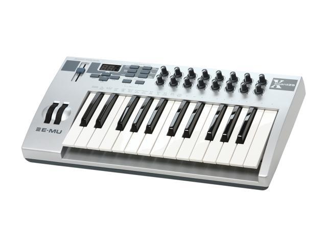

- #XBOARD ILLUMINATORS REVIEW DRIVER#
- #XBOARD ILLUMINATORS REVIEW FULL#
- #XBOARD ILLUMINATORS REVIEW PC#
Tools: Soldering station and solder Clippers Helping hands Wire strippers Programming / Debugging Tools: PC with Arduino IDE installed USB to UART adaptor (I use a cheap CP2102.
#XBOARD ILLUMINATORS REVIEW DRIVER#
from UPU's store) 1 x GPS breakout board with antenna (the board is designed for this one) 1 x SD card breakout board (e-bay)* 1 x board-mount DS1820 temperature sensor* 1 x external DS1820 Temperature sensor (e-bay)* 1 x HoneyWell HSCDANN001BA2A3 board-mount absolute pressure sensor (Mouser)* 1 x tactile switch 3 x 100nf ceramic caps 1 x 100 uf electrolytic cap 1 x MCP1825 ultra-low dropout 3v3 regulator 1K resistors (around 5) 10K resistors (2-3) 4k7 resistors (4-5) 3mm LEDs (0-4 according to preference, different colours)* Selection of 1% resistors (I used: 47K/6.8K for the battery sensor and 6.8K/10K for the radio driver ) Male header pins (0.1") - some straight, some 90' There may well be better options but this worked well for me: Materials: 1 x Custom Tracker Board (see next step) 1 x ATMega 328** 1 x 8MHz Crystal (NB not the usual 16MHz) 2 x 22 pf ceramic caps 1 x Radiometrix NTX2 (e.g. These are the materials I used for my design. The design files for the tracker board and more details on the design are in the later steps. This means that it can be fabricated on some incredibly cheap PCB fab' sites. The tracker is designed on a custom PCB which is 5 x 5 cm in size.


#XBOARD ILLUMINATORS REVIEW FULL#
That means that we can't clock the '328 up to its full 16MHz but it will run happily at 8MHz on 3v3, and that's plenty for our purposes. Because the GPS module and SD card both require 3.3v and we have plenty of computing power, we may as well make the whole tracker run on 3v3. We are going to make an "Arduino Compatible" board which we can program using the Arduino IDE. The tracker is based upon the Atmel ATMeag328 Microcontroller which forms the heart of many of the popular "Arduino" boards. The guys at UKHAS are fantastically helpful. If you live elsewhere or you are doing this significantly after I write this instructable, please check the rules that apply to you. The approach I will use in this instructable is suitable for the UK under the rules prevailing in 2013. There are plenty of rules and regulations regarding what you can fly and which parts of the radio spectrum you can use for various tasks.

That is what I will outline in this instructable. In order to take advantage of this wonderful network of helpers, we need to build a tracker that will communicate with their equipment. Fortunately, at least in the UK and increasingly across Europe, the very helpful guys at the UK High Altitude Society () have developed a distributed network of trackers who will receive a signal from your balloon, upload the data to a server and plot the position for you on a Google Maps based page (/tracker/). In order to see the photos that you have taken, you then need to find the camera afterwards. low pressure at the edge of the atmosphere) and then it will fall back to earth. This is easy enough: you attach it to a massive balloon, let it rise until the balloon bursts (due to the v. Ours went 38Km (124,000 feet) straight up. In order to take this kind of photo you need to send a camera up to the stratosphere. I'm having trouble embedding it so the link is here The Flickr set with the photos from our first launch is here: This is a quick-fire slideshow of the photos from the balloon, formatted as a 2.5 frames/sec video. That's not quite into space itself (100Km+) but so high that the sky looks black and you can start to see the curvature of the earth as the globe rolls away below you. One of the coolest projects I have done so-far with my kids is a "near-space" balloon.


 0 kommentar(er)
